
Items
All the items added in the Proposal Designer will populate on the left side of the screen. Drag and drop the items onto the background image to add them. From there, you can resize and rename them accordingly. Once an item has been added, it will appear green in the item menu on the left.
The Item Menu looks like this:

Master Item Details
To find this you will go to Designer < click on the item to bring up more options < click on master < then navigate to Engineering Tab. There are many sections on the Engineering tab and we will go over them below.
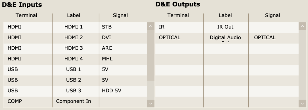
Inputs & Outputs
This is where we will enter all of the Inputs & Outputs on a specific item. The Terminal box is where you will enter what type of connection it is. The Label box is where you insert a name for the input or output. The Signal box is where you will enter the function for a specific input (Ex: We have an HDMI input labeled HDMI 3 and it’s the ARC input for this specific item). Refer to image below as a reference for setting up Inputs & Outputs.
D&E Wire
The D&E Wire checkbox is located in the bottom right of the Engineering tab and this will make an item function as a wire in Design & Engineering. Once selected, you’ll be able to drag that item on to your design and connect it to other items. In the example below, a Line Drawing is used to show the basic connections between 3 speakers and a receiver. You can also change the color of the wire by selecting the pencil icon on the Navigation Bar at the top. ![]()

Custom Icons
There are 3 different types of custom icons and they correlate to the different types of drawings. To add a Custom Icon you can right click in one of the icon boxes or drag and drop an image into the boxes. You can delete the icon by clicking on it and pressing the delete key on your computer. Once added, you can head to your design and add that item to correct type of drawing and you will see the custom icon appear in the drawing. In the image below you can see that I’ve added a custom Line and Plan icon. Note: this icon can be a custom image, in lieu of a general icon.
![]()
Racks
Racks have a little more functionality than other items in Design & Engineering. Head to the Engineering tab in Item Details of the item you want to use as a rack and you’ll see two settings that need to be changed for the item to be setup correctly.

You’ll want to make sure you have the setting “Rack Cabinet” checked and that you have the correct number of rack spaces selected. The example in the picture above has 15 rack spaces so we put a 15 in that box. You can also add custom icons here, but we don’t recommend adding an elevation custom icon as we have a default icon for that specific type of drawing.
For items that are typically mounted in racks, you’ll want to check the box labeled “Rack Mounted” and add how many rack units it takes up. The example below is a router that can be rack mounted and it takes up 1 rack unit.

Here is an example of a rack in elevation mode. You can see that it has numbers for each rack space and items automatically snap to a rack space when they are dragged into a rack.

*If you have questions regarding Items in Design & Engineering please contact our support team and they will be happy to assist you.